Auduino mod
Summary
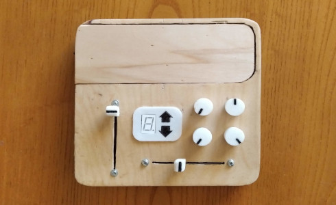
Auduino is an old project - more information about it is available here. It is a synthesizer based on the Arduino UNO. It uses a technique called granular synthesis to produce very interesting sounds. In this project some weaknesses of the synthesizer are addressed and modifications are made to compensate for them.
How it sounds
The modded Auduino has a more mellow sound timbre from the original, it can produce a more groovy melody with variable volume dynamics and the musical scale it uses is displayed and can be changed with the push of a button.
About the Auduino
The Auduino produces sound by adding two decaying triangle waves together and repeating them as often as the user chooses. The two decaying triangle waves make up the grain and the frequency of its repetition (grain frequency) defines the primary note.
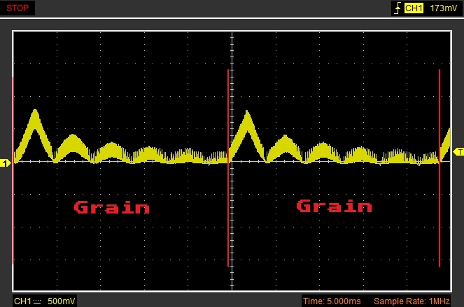
To make the example easier to follow only one of the triangle waves was used in the image. Also, this oscillation is not the direct output of the arduino. The PWM output was filtered through a low pass filter in order to make the oscillations visually clearer.
In the above image the Auduino's output was probed. It is evident that there is a triangle wave that slowly decays and that it is being repeated after some time. These are two grains of the synthesis.
By altering the frequency and decay time of the triangle wave, it is possible to emphasize on certain harmonics of the primary note (defined by the grain frequency). By utilizing both the available triangle waves that make up one grain in the Auduino, it is possible to synthesize a note and emphasize on two different regions of its harmonic content.
Looking again at the Auduino output above it is evident that the grain repeats every 25ms - that makes a grain frequency of 40Hz and thus a note of 40Hz or an E1. It is also easy to observe that the triangle wave's frequency is 5.5 times greater than the grain frequency. It is then expected that the output will sound like an E1 with rich sound in its 5th and 6th harmonic regions.
There are originally five controls for this synthesizer
- Frequency of triangle wave 1 (harmonics to emphasize)
- Decay of triangle wave 1 (how much emphasis)
- Frequency of triangle wave 2 (harmonics to emphasize)
- Decay of triangle wave 2 (how much emphasis)
- Grain frequency (primary note that is being played)
The Auduino uses an analog output(PWM) in order to produce a wave of variable magnitude. The analog output is altered about 32000 times a second in an interrupt sub routine - this means the output has a sample rate of about 32KHz.
Rhythm
The Auduino synthesizer produces a tone that is continuous and constant in volume. This is why it is very difficult to produce a melody that has rhythm.
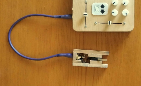
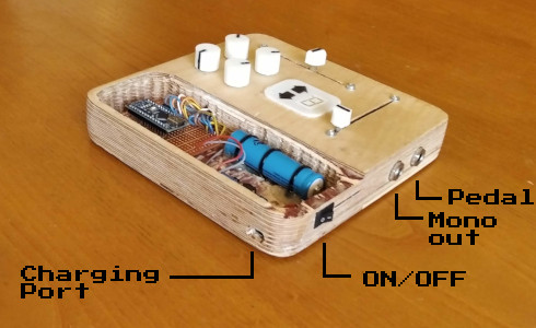
In order to address that problem a sound pedal was added. The sound pedal is nothing more than a switch much like the sustain pedal on a piano. When held down (closed switch), the synthesizer produces sound and when it is up (open switch), the sound stops. The starting and stopping of the sound was written in a way that prevents output discontinuity.
The pedal used was a small DIY project that is available here.
Dynamics
After addressing the rhythm problem(which is arguably the most important aspect of music), it is time to work on dynamics. There are two options here:
- An ADSR envelope written in code that activates every time the pedal is pressed
- A simple volume slider so that the volume of each note can be adjusted by hand
The second solution was chosen because it offers more freedom to the player. It may also be more difficult to use than an automated ADSR but since the player is supposed to have both hands free, it is a viable solution.
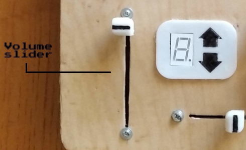
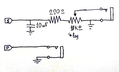
A logarithmic 10KOhm slider potentiometer was used for that purpose.
Note consistency
It is a bit difficult to land on a desired note on the original Auduino because of two reasons:
- A very small movement of the potentiometer corresponds to a note change
- The input of the potentiometer is noisy and there are areas of the potentiometer where the output oscillates between neighboring notes.
To address the first problem, the range of the synthesizer was shrank to about 5 octaves. The very low octaves and also most of the high octaves were removed. The sound at extreme bass and treble octaves is not great to begin with so this is not a big sacrifice. On top of that, a large slider potentiometer was used to increase the user's accuracy in selecting notes.
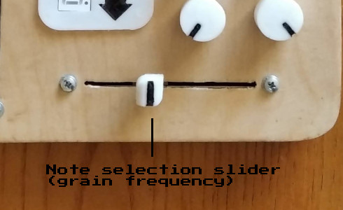
To deal with the second problem, the input of the potentiometer that is responsible for the note change is filtered using a method called a rolling mean(or moving average). It is a low-pass filter that can be easily implemented in code.
This method of filtering works by taking the average of a number of N values from the original input. These N values are stored in a LIFO fashion. Also important for designing the filter is the sampling frequency of the original input - that means how often a new value from the input enters the LIFO structure.
The cutoff frequency of the rolling mean can be estimated using the equations that follow. It depends on the number of input values that are being averaged(N) and the sampling frequency(fs). Equation (1) gives the normalized frequency - the cutoff frequency in Hz is calculated using equation (2).

The downside of using a moving average filter is that it slows down the responsiveness of the control. In order to keep the response time low, N was chosen to be 8 and a sampling rate of 500Hz was used. Using the formulas these values give a cutoff frequency of about 28Hz which is more than enough to improve the noise problem.
Musical scales
The original synthesizer could be programmed to use either a pentatonic scale or the chromatic scale. This is a bit of a handicap since the chromatic scale is difficult to use by adjusting a potentiometer and using only one of the 12 pentatonic scales is not guaranteed to be in tune with a song.
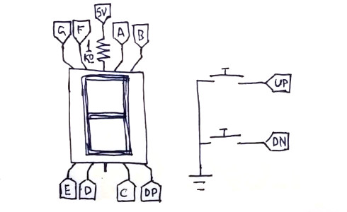
In order to tackle this, the synthesizer was equipped with a display for showing the current scale's key note and two buttons for changing it. The user can select between every pentatonic scale and the chromatic scale. The code can be altered to add any other desireable scale.
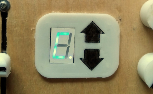
The display's "dot" symbol is used to represent a musical sharp(#) symbol. In that sense, in the image above the display is read as C# and it corresponds to a C# minor pentatonic scale. Additional functionality can be added to the buttons by implementing long button presses.
Output discontinuity
The synthesizer is prone to outputting waves that are discontinuous at the end of grains. That gives some notes a timbre that resembles a sawtooth wave and makes them sound harsh. This discontinuity is visible in the next image and the resemblance to a sawtooth wave is visible.
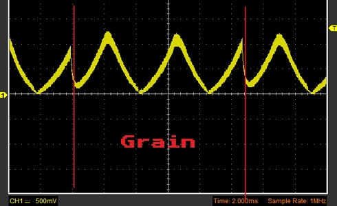
Here is how that discontinuity sounds like:
A technique that can be used to eliminate this behavior is introducing a small linear fade-out tens of samples before the end of each grain. After implementing the fadeout, the discontinuity disappears and the sound is much more mellow.
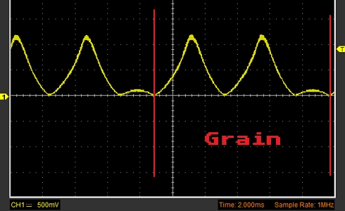
Here is how eliminating the discontinuity sounds like:
Having this sawtooth-like quality appear in the sound could be someone's preference. The grain fade-out can be easily commented out in the Arduino code.
Features
These are the features of the final build:
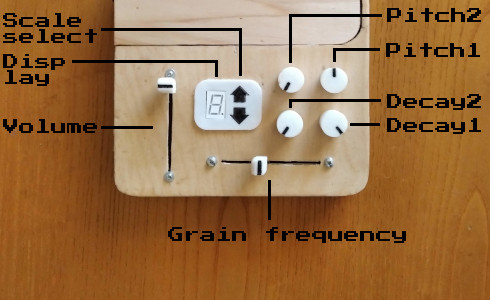
The arduino is easily accessible for re-programming. The wooden lid that covers the top portion of the synth slides out.
Code
The original Auduino code was reworked using the Arduino IDE. These are the features that were added in the program:
- Output disable based on digital input pin state for the pedal
- A moving average filter for the grain frequency ADC input
- Reduced range for the grain frequency
- A system for cycling through scales of different key
- Seven segment display communication
- Software debounced pushbutton reading (for changing scales)
- Grain fade out
The code is available for download here.
Schematic
The schematic is identical to the original Auduino except for the extra components that are used. This means that eight extra pins from the arduino are used for the display, two more pins are used for the buttons and one extra pin is used to read the pedal position.
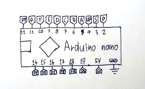
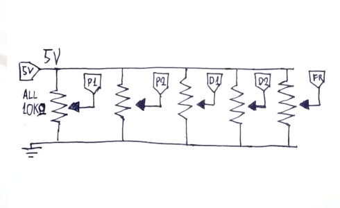
A simple low pass filter is used before outputting the signal to the output female jack. Another female jack is used for the pedal input.
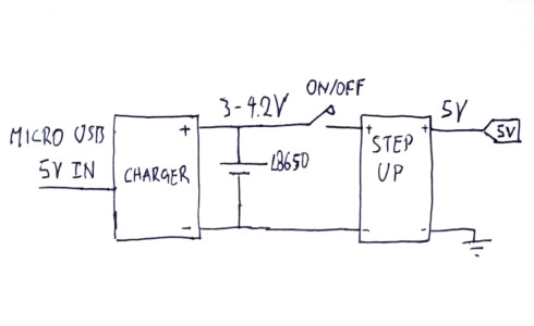
The Arduino is powered through a step-up converter at 5V. The converter is powered by a 18650 lithium battery. The battery is also connected to a charging board that is able to recharge the battery through a micro USB connector.
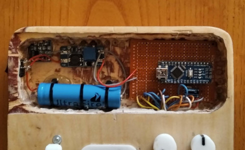
Circuit
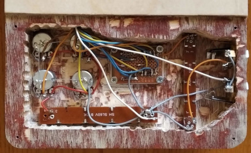
A small prototyping board was used to mount the arduino and the low pass filter. Everything else was soldered together with wires. Hot glue was used for securing the battery and the circuit boards in place.
Casing
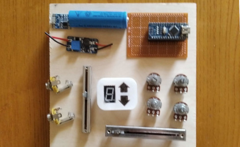
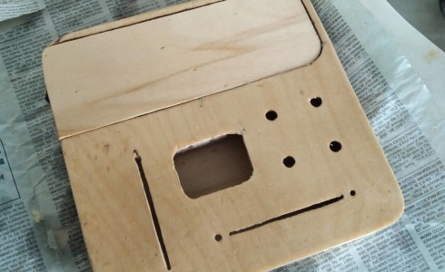
The casing was carved out of a piece of plywood. The electronics were placed freely in order to find a good place for everything.
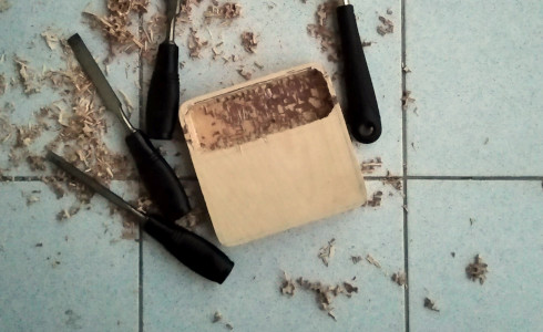
A power-drill and some chisels were used to hollow the wood for installing the electronics.
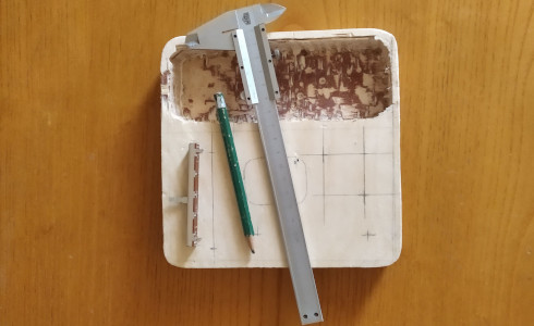
Afterwards the location and holes for every component was marked down with a pencil.
After giving the casing its final form, it was coated with linseed oil.
3D printed parts
All the potentiometer knobs for this projects were 3D printed and painted by hand. The display's cover was also 3D-printed along with some flexible button covers. The circuit board with the display and the buttons is fastened behind it with screws.

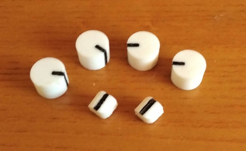
All the parts are available for download in STL form here.
