Stepper motor math model
Summary
A stepper motor is a special kind of brushless DC motor. It can execute precise movements without the need of a closed loop control system or a sensor. In this page a mathematical model of such a motor is derived and the model's parameters are examined and tuned so that the model's performance mimics the actual performance of the motor.
Motor used
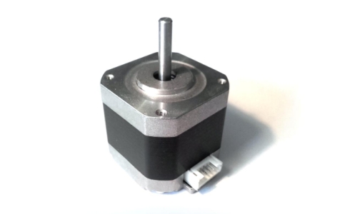
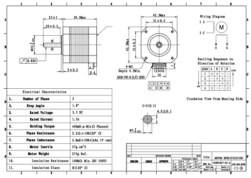
This model focuses on a NEMA 17 stepper motor but the process followed is similar for modelling other stepper motors as well. The exact motor used is described by the code name 42HD4027-01 under the NEMA standard. The last section in this page - Motor design - includes mechanical drawings, photos and the datasheet of this stepper motor.
Model block diagram
Inputs
This stepper motor has two separate phases. Therefore, the main inputs for the model are the two voltage differentials applied to each of the two phases. Other secondary inputs are the moment of inertia of the load attached to the motor and any external torques applied to the load and/or motor shaft. Also some inputs in the form of initial conditions are the initial angular position and speed of the rotor and the initial currents in each phase.
The friction in the motor is neglected in this model but it can easily be implemented as an external source of torque.
Outputs
After solving the differential equations of the model, the kinematic response of the rotor can be extracted as well as the electric response of the phases. On the kinematic side, the outputs are the angular position, speed, acceleration, jerk(or rate of change of acceleration) and torque. The electric response includes phase current and voltage induced by the spinning magnetic rotor.
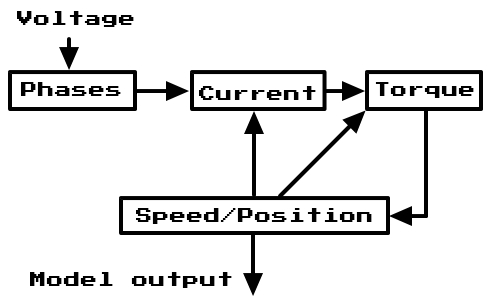
The above diagram shows the main idea of this model:
- Voltage is applied to the phases
- That generates current in the phases
- Phases run with current generate torque on the motor's shaft
- Torque on the shaft rotates it, changing its speed and position
- The speed and position of the motor's shaft affect both the torque applied by the phases and the current in the phases
Physics
These are the basic physics laws used to describe the behavior of the motor:
-
Newton's second law for rotation
The torque applied is directly proportional to the moment of inertia times the angular acceleration.
-
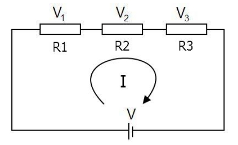
kirchhoff's second law
The directed sum of the voltages around any closed loop is zero.
-
Faraday's law of induction
The EMF induced in a conductor is given by the rate of change of the magnetic flux in it.
Apart from the above well known and broadly applicable theorems, there are a few equations that specifically describe the behavior of this stepper motor:
-
Phase current/max torque linear dependency
A phase's current is linearly dependent to the maximum torque the phase can exert to the rotor. Therefore, the two can be related to each other by the use of one constant (
-
Phase torque
The torque a phase exerts on the rotor depends on the phase current as well as on the rotor's position. This happens because of the way the motor is built - due to geometric characteristics of the rotor and the stator.
-
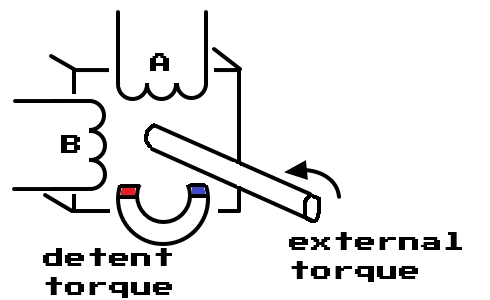
Detent torque
This is a "parasitic" torque that exists due to the magnetic rotor. It is small in magnitude compared to the motor's maximum holding torque but should still be accounted in the model since it interferes significantly with the positioning and movements of the rotor.
-
Rate of change of magnetic flux linkage between one phase and the rotor
This rate is important because, according to Faraday's law, it corresponds to the induced EMF in the phase.
Shaping the equations
In order to derive the model of this system, every equation that describes its nature must be related to each other. Initially, the total torque exerted on the rotor can be expressed as:
After substituting the known equations for
The two expressions for the torques
Kirchhoff's 2nd law can be applied for each of the two phases of the motor:
Phase A
Phase B
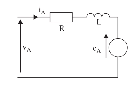
According to Faraday's law (
Phase A
Phase B
The two expressions for the induced voltages
At this point, equations
Equation parameters
The parameters in equation
-
The parameters in equations
Changing the values of these parameters will affect the behavior of the model. In order to tune these parameters so that the model mimics the behavior of the motor, their values must be derived from the motor's characteristics. This is possible by either making measurements on the motor or by consulting the motor's datasheet. Unfortunately, not all information needed is always available in the datasheet, so some measurements are often required.
Tuning the parameters
The parameters can be tuned by either consulting the motor's datasheet or taking measurements on the motor.
-
It is usually given in the motor's datasheet but can also be calculated from the rotor's geometry.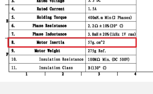
-
Can be arbitrarily chosen or should be calculated for a specific load based on the load characteristics. -
Revisiting equation
Where:
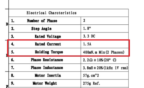 Manufacturers probably prefer to display the two phase holding torque in the datasheet because it
has a bigger value.
-
The rotor has as many teeth as a quarter of the steps the motor can execute in a full circle (360°).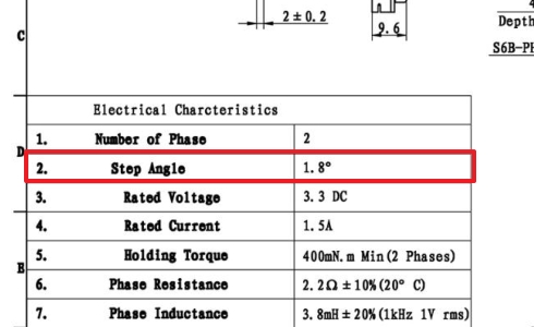 Consequently, for a step angle of 1.8°:
Alternatively, the teeth of the rotor can be counted by eye. The left side only should be counted.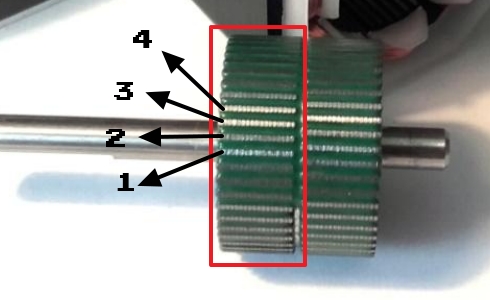
-
This value is rarely if ever given in the datasheet. The maximum torque the motor exerts when both phases are inactive (0 current) is the maximum detent torque. It can be measured with a precision scale by placing the motor on a jig as shown in the next image: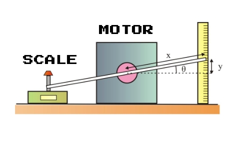 Alternatively, it can be estimated to be about 2% of the motor's two phase holding torque (this
percentage gets smaller for bigger motors).
-
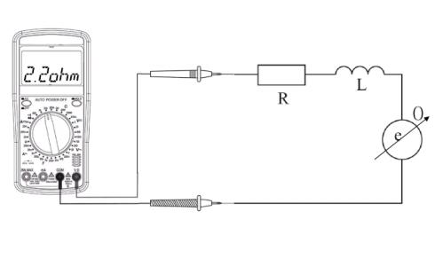
The motor's phase resistance is given in the datasheet and can be easily measured using a multimeter.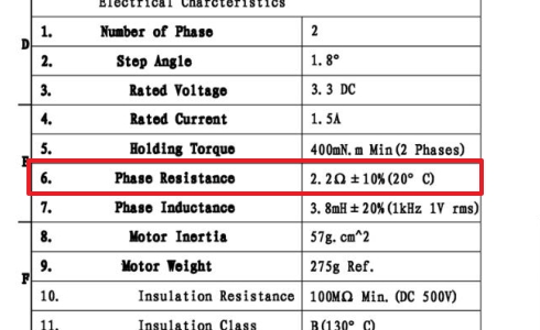
-
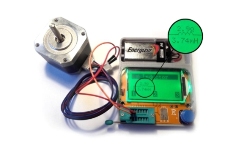
The motor's phase inductance is also given in the datasheet and can be easily measured using an LCR meter.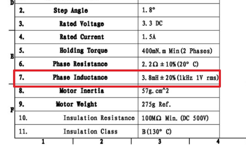
-
This value will most probably not be in the datasheet and cannot be estimated based on other information in it. There are several ways to calculate it but they require some tools. The main concept is measuring the signal produced in a phase when the rotor is rotated and then deriving the maximum flux linkage based on that signal.-
Oscilloscope methods
The probes of the oscilloscope are tied to a phase of the motor. The motor's shaft is rotated at a constant speed with a help of an external motor (e.g. a hand drill). The induced voltage is measured - it has the shape of a sine wave.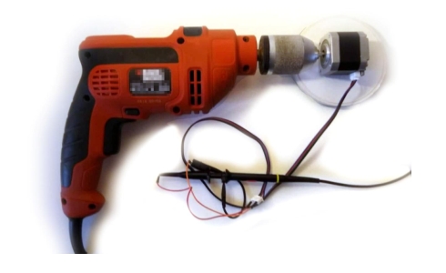
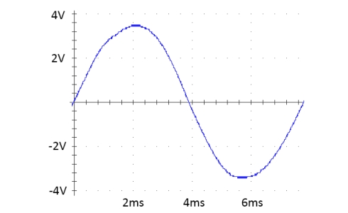 This induced sine wave is described by equation
Therefore, the maximum flux linkage between the rotor and a phase can be calculated by the angular speed of the rotor(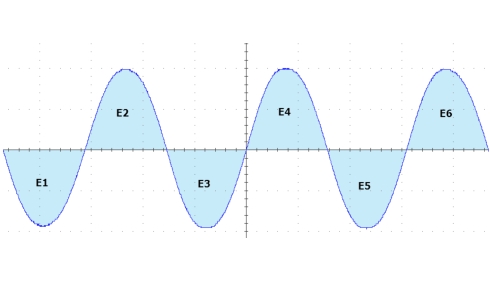
-
Multimeter and tachometer
An estimation of the magnetic flux linkage can be made using these simpler tools. In this case the multimeter is used to measure the RMS value of the induced sine wave and the tachometer is used to measure the speed of the rotation.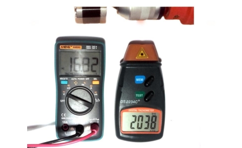 Afterwards, the maximum induced voltage can be calculated by multiplying the RMS value by
-
Oscilloscope methods
Solving the model
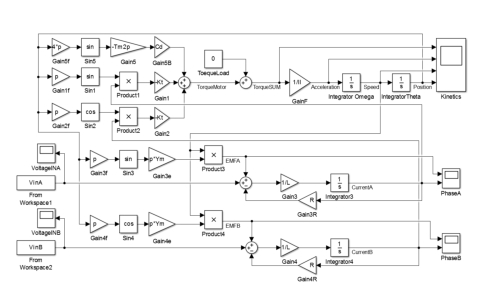
After having created an accurate model, it must be solved. The best way to tackle this is using a firmware such as Simulink of Matlab or Xcos of Scilab. The following image shows an implementation of the above model in Simulink:
Motor design
Assembled motor:

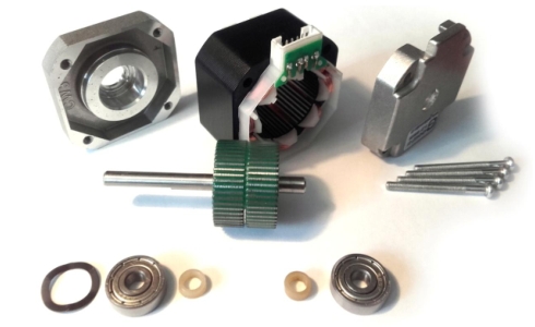
Disassembled motor:
Exploded view:
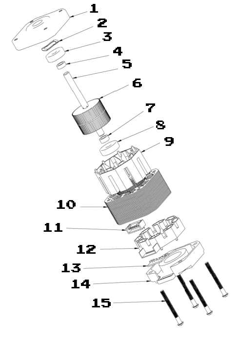
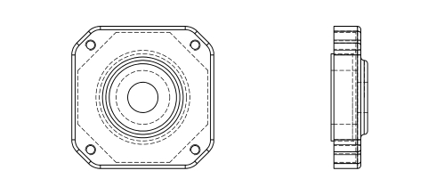
Parts:
-
Cover B
-
Wave washer

-
Bearing

-
Spacer B

-
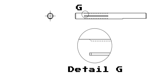
Axel
-
Rotor assembly

-
Spacer A

-
Bearing

-
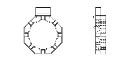
Insulation A
-
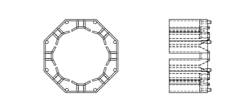
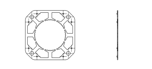
Stator punched sheet metal
-
JST connector

-
Insulation B
-
THT board

-
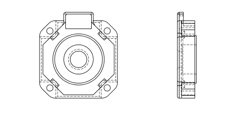
Cap A
-
Phillips screw

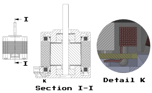
Section view:
Datasheet:
Sources
This page is a summary of part of the thesis "Stepper motors and simulation of their operation" available as a PDF here.
