Origami light 2
Summary
Origami light is a project about fitting a modular origami with sensors and lights, essentially turning it into a useful ornament. This is an attempt to make this gadget easier to manufacture and fix some of the weak spots it had. In this page there is information about each change that was made and files for printing and producing this version.

Any color transparent paper can be used to make the origami!

The light can also be customized but more common types of lights are red, green, blue, white and warm white.

The origami can be recharged with a usb-c charger, plug it in until the red light turns off.

I sometimes build and sell some pieces on eBay. Check this link for availability.
Original project issues
The original origami light has these main weaknesses:
- Over-engineered and heavy chassis
- Hard to access charging port
- Difficult to make circuit
- Potentially high leakage current on sleep
- Low battery indication
Over-engineered and heavy chassis
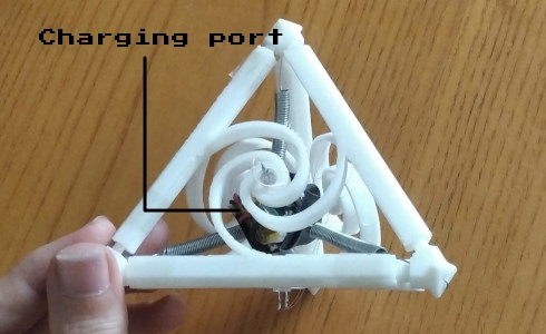
Although the idea for the original chassis was fun to make and came with a practical use, it is better to stick with a simpler, lighter design since it is viable. Here is how the old chassis looked like:
Hard to access charging port
For the construction of the original origami, an off the shelf lithium battery charging board was used. That resulted in the charging port being located inside the origami, in the center of the chassis. This means that in order to charge its battery, the origami must be disassembled, which is not very practical.
Difficult to make circuit
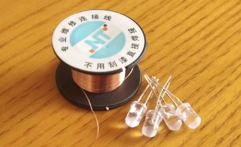
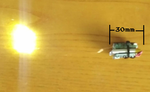
There are many aspects to why the original circuit is difficult to make. Some reasons may be soldering thin copper wires onto 3mm LEDS or fitting large THT components as tightly as possible. A circuit like this is also hard to make copies of.
Potentially high leakage current on sleep
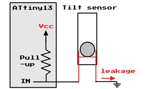
The original circuitry implemented a metal bead tilt sensor. Unfortunately, a flaw of that sensor was overseen when designing the prototype. When the sensor is in its close position, it results in considerable leakage current that can greatly reduce the battery life in sleep mode. This happens because the internal pull-up resistor remains active in sleep mode.
Low battery indication
The original design has no way of indicating the battery level.
New chassis
A new chassis was designed with the disadvantages of the original one in mind. The design was made in Fusion360.
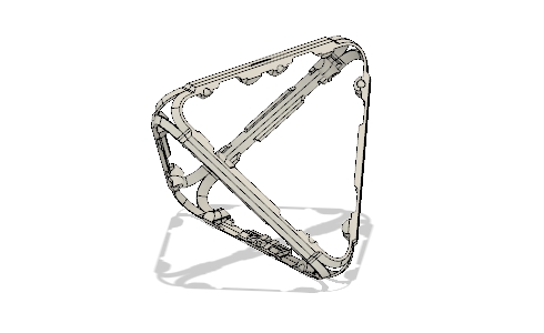
The new design has no moving parts but fits tightly inside the origami. Furthermore, it has half the part count and it is much lighter and faster to 3D print. Finally, some flexible areas were intentionally added to improve the chassis' resistance to shock or fall damage.

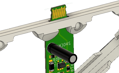
The PCB is easily attached to the chassis while the battery is attached using two small zip-ties. The 250mAh li-polymer battery was also swapped out for a 800mAh 14500 battery which, apart from the bigger capacity, has standardized dimensions and is easier to find.
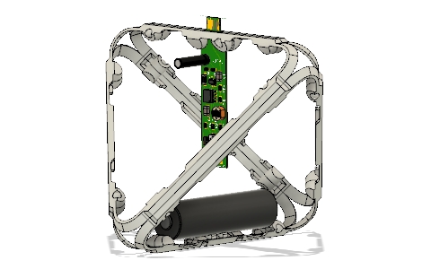
This is the chassis assembly with the battery attached and a mockup of the PCB:
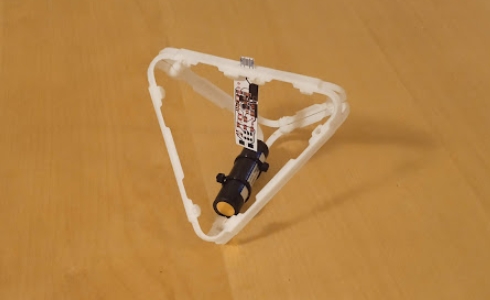
The chassis is made of 2 different parts that are printed two times each for a total of 4 parts, in order to create the tetrahedral chassis. The STL files for these parts can be downloaded here.
Printed circuit board
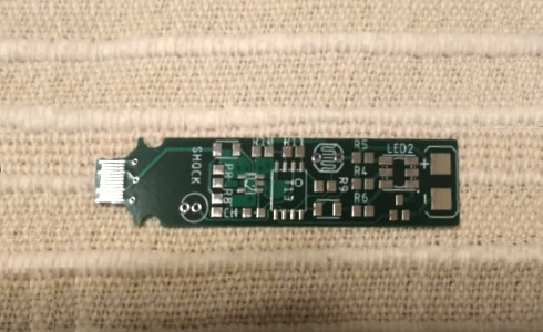
The circuit was reviewed and everything was integrated in a small 0.6mm thick PCB design in Eagle. Every component that could be purchased as SMD was swapped for a smaller package. Instead of using a separate battery charging board, the battery charging IC was also included in the design.
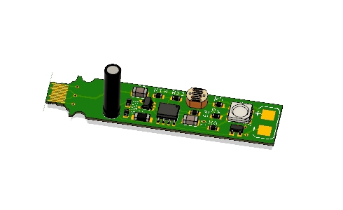
A female USB-C is etched on board and is designed to be protruding to the outside of the origami. This way the battery can be charged without disassembling the origami. The chassis is designed with the shape of the PCB in mind - they lock onto each other without the need for extra fasteners.
The gerber and drill files for the board can be downloaded as a zip file here. The 0.6mm thick PCB was ordered by JLCPCB.
Circuit changes
These are the changes made to the circuit:
- A voltage divider to the battery was added so that the microcontroller can read the battery level using its internal voltage reference and communicate it to the user by blinking the origami's LEDs.
- The battery's voltage divider as well as the photoresistor divider are grounded through an I/O pin. That gives the advantage of disconnecting them from ground when they are not read, in order to decrease their leakage current during sleep mode.
- The tilt sensor cannot be disconnected since it must remain active during sleep. It was therefore swapped out for another type of sensor (shock sensor) that is normally open, decreasing considerable leakage current.
- Instead of 4 3mm LEDs, two 5050 SMD LEDs are used on either side of the board. In order to support the bigger load, an N-MOSFET was chosen rather than driving the LEDs directly from the microcontroller's pin.
- The charging IC was added to the circuit rather than using an external lithium battery charging module.
Autodesk's EAGLE was used to make the schematic and the board design.
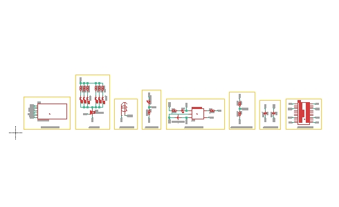
The BOM for this board can be found here.
Code changes
The new features that were added to the code were:
- Reading the battery level with ADC's internal bandgap reference.
- Outputting the low battery level to the user.
- Using the RST pin as a digital ground to disconnect unused sensors, decreasing leakage current.
- Interfacing the ATtiny13 with the charging IC to deactivate all processes while charging. This helps achieve a better, healthier battery charge.
Since the ATTiny13 only has 1K bytes of flash for all these new features, the code was changed substantially in order to reduce its size and fit everything onto the chip. The C++ code is well commented and can be downloaded along with the .hex file here.
The code is also available on github here.
Licensing
This project is licensed under the Creative Commons BY-NC-SA 4.0.
